Agro -25%
Popular


In Stock
Product Code: ID8618
28 767₴
Found cheaper?


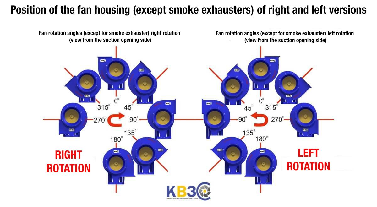
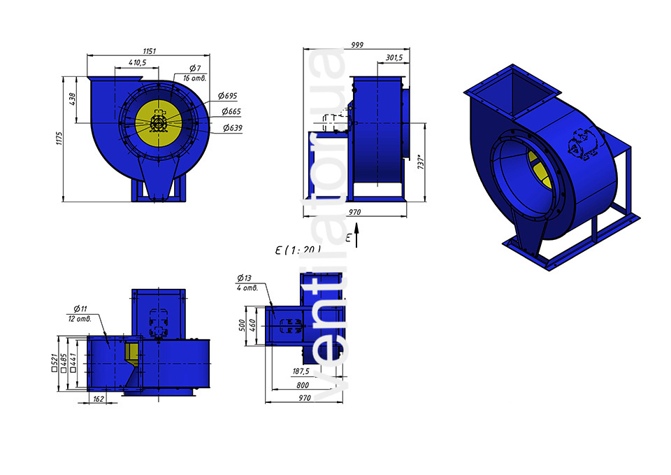
Low-pressure centrifugal fan VC 4-75 #6.3 w/motor AIR 90 L6 1.5 kW 1000 rpm for general industrial applications, manufactured according to design scheme No. 1 from carbon steel.
Productivity, м³/h:3190
Pressure, Pa:465