Low-pressure centrifugal fan series VC 4-75 #4 with electric motor Electric motor 4VR 90 L4 2.2 Power kW 1500 Vol./Min, manufactured according to the scheme of execution #1 of dissimilar materials for explosive environments.
Fan working point: 3800 m3/hour at a pressure of 400 Pa.
VC 4-75 VZ #4 w/motor 4VR 90 L4 2.2 kW 1500 rpm, execution 1
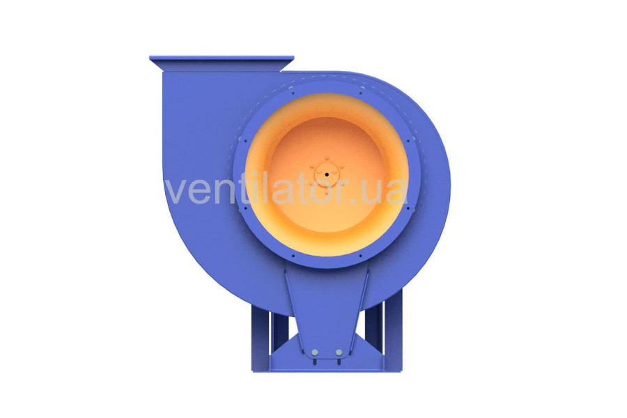
Low pressure centrifugal fan


Low-pressure centrifugal fan of the VC 4-75 #4 series (VR 88-72.1-5.5, VR 80-75-5) with electric motor Electric motor 4VR 90 L4 2.2 Power kW 1500 Vol./Min made of dissimilar materials for explosive environments
This fan is designed for ventilation or air conditioning systems operating with explosive gas-vapor-air mixtures of categories 1 and 2, groups T1, T2, T3 according to the "Rules for Electrical Installations" (PUE), which do not cause accelerated corrosion of materials in the fan’s flow part. These mixtures must not exceed a temperature of 80 °C, and the content of fibrous materials, sticky substances, dust, and other solid impurities must not exceed 100 mg/m³ in moderate (U) climate conditions (placement category 3) and tropical (T) climate (placement category 2), in accordance with DSTU 15150. Permissible ambient temperature ranges from -40 °C to +40 °C (+40 °C when equipped with tropical-design electric motors).
The casing and impeller blades of explosion-proof fans are made from material pairs (steel-brass or steel-aluminum) that are not hazardous in terms of ignition from friction sparks according to DSTU 22782.0-81.
The centrifugal fan VC 4-75 #4 (VR 88-72.1-5.5, VR 80-75-5) consists of the following units that can be purchased separately:
- Fan VC 4-75 #4 (VR 88-72.1-5.5, VR 80-75-5) without electric motor
- Impeller VC 4-75 #4 (VR 88-72.1-5.5)
- Casing (shell) of the fan VC 4-75 #4 (VR 80-75-5)
- Electric motor Electric motor 4VR 90 L4 2.2 Power kW 1500 Vol./Min for fan VC 4-75 #4
General information about centrifugal fans VC 4-75 #4 (VR 88-72.1-5.5, VR 80-75-5) with electric motor Electric motor 4VR 90 L4 2.2 Power kW 1500 Vol./Min made from dissimilar metals:
- Low pressure
- Single-sided suction
- Backward-curved blades
- Number of blades: 12
- Rotation direction: right and left
- Manufactured according to TU U 28.2-24881057-003:2023
- Material: dissimilar metals
Purpose of centrifugal fans VC 4-75 VZ #4 w/motor 4VR 90 L4 2.2 kW 1500 rpm (VR 88-72.1-5.5, VR 80-75-5):
This fan is intended for ventilation or air conditioning systems operating with explosive gas-vapor-air mixtures of categories 1 and 2, groups T1, T2, T3 according to the "Rules for Electrical Installations" (PUE), which do not cause accelerated corrosion of materials in the fan’s flow part. These mixtures must not exceed a temperature of 80 °C, and the content of fibrous materials, sticky substances, dust, and other solid impurities must not exceed 100 mg/m³ in moderate (U) climate conditions (placement category 3) and tropical (T) climate (placement category 2), in accordance with GOST 15150. Ambient temperature is allowed from -40 °C to +40 °C (+40 °C when equipped with tropical-design electric motors).
Applications of centrifugal fans VC 4-75 VZ #4 w/motor 4VR 90 L4 2.2 kW 1500 rpm (VR 88-72.1-5.5, VR 80-75-5):
- Air conditioning systems
- Ventilation systems
- Air heating systems
- Other sanitary and industrial applications
The centrifugal fan VC 4-75 VZ #4 w/motor 4VR 90 L4 2.2 kW 1500 rpm (VR 88-72.1-5.5, VR 80-75-5) operates in moderate climate conditions with ambient temperatures ranging from -40 °C to +40 °C. The temperature of the transported medium must not exceed 80 °C.
Operating principle of the centrifugal fan VC 4-75 VZ #4 w/motor 4VR 90 L4 2.2 kW 1500 rpm (VR 88-72.1-5.5, VR 80-75-5):
Air enters the fan under the influence of centrifugal force at a 90° angle after receiving energy from the impeller blades and moves radially toward the spiral casing. While moving along the spiral-shaped casing, the air is directed under pressure through the fan exhaust.
Completeness of the centrifugal fan VC 4-75 #4 made from dissimilar metals:
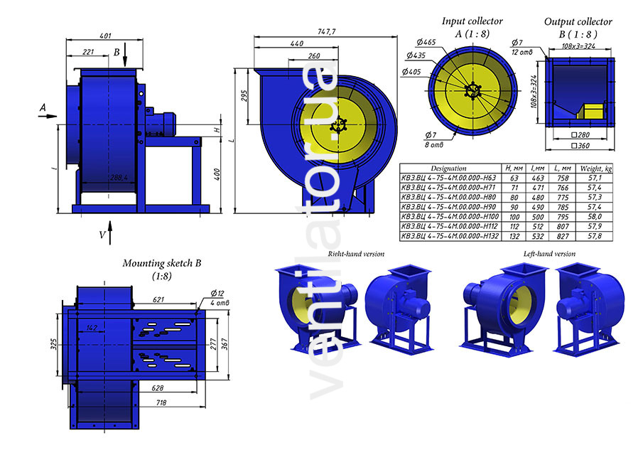
The fan VC 4-75 #4 (VR 88-72.1-5.5, VR 80-75-5) with electric motor Electric motor 4VR 90 L4 2.2 Power kW 1500 Vol./Min consists of the following main components:
- Spiral casing
- Impeller
- Frame
- Collector
- Electric motor Electric motor 4VR 90 L4 2.2 Power kW 1500 Vol./Min
The impeller consists of a front and rear disc, 12 sheet blades, and a hub.
The fan frame is welded. The base includes an opening for installation on vibration isolators or a foundation. The electric motor and cover are mounted on the frame.
The conical collector for supplying air to the impeller is mounted on the inlet pipe. The gap between the collector and the front disc of the impeller is adjusted by axially shifting the collector within the inlet pipe.
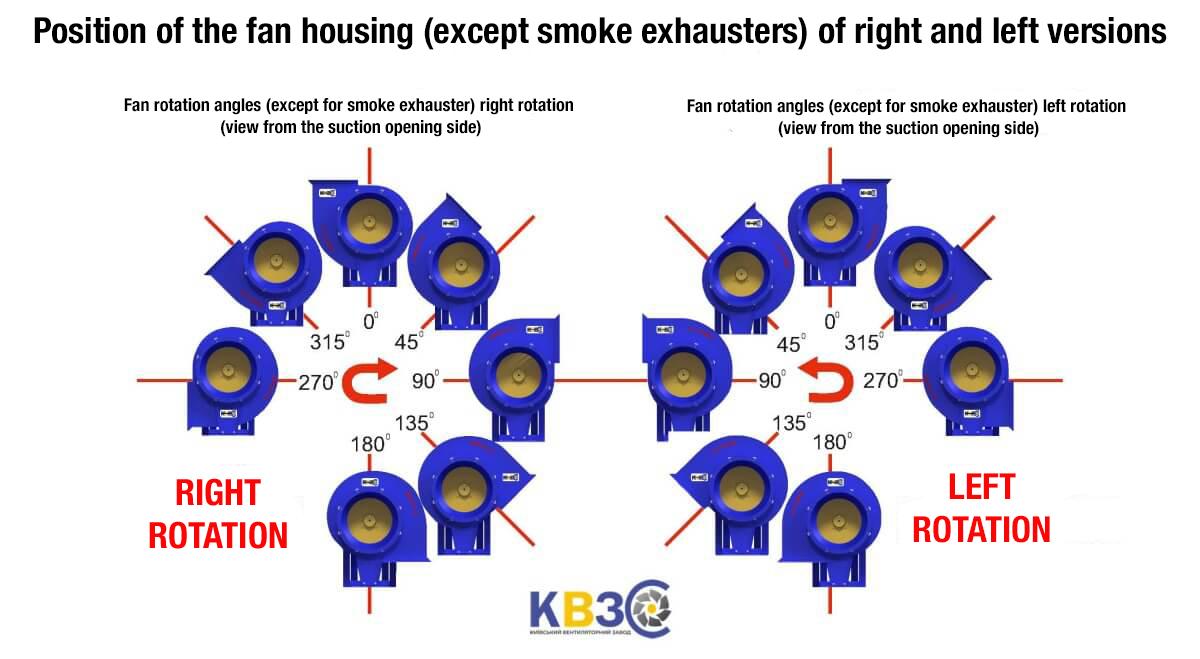
Fan casing positions (viewed from the suction side):
- a) Right-hand rotation
- b) Left-hand rotation
Note on placement categories based on climate conditions:
Category 1: For outdoor use (exposed to all climate factors typical of the given macroclimatic regions).
Category 2: For use under a canopy or in spaces with free access to outside air, such as tents, trailers, metal structures without insulation, and enclosures of category 1 devices (no direct exposure to sunlight or precipitation).
Category 3: For enclosed spaces with natural ventilation and without artificially controlled climate, such as insulated metal, stone, concrete, or wooden premises (no exposure to precipitation or sunlight; significantly reduced wind; minimal or no exposure to diffused sunlight and moisture condensation).
Category 4: For spaces with artificially controlled climate, such as heated, cooled, and ventilated production premises, or well-ventilated underground areas (no exposure to sunlight, precipitation, wind, sand, or outdoor dust; minimal or no diffused sunlight and moisture condensation).
Category 5: For spaces with high humidity (e.g., unheated and non-ventilated underground areas such as mines, basements, soil-based enclosures, ship compartments, or areas where water presence or frequent condensation occurs, including certain holds and workshops in textile or hydrometallurgical industries).
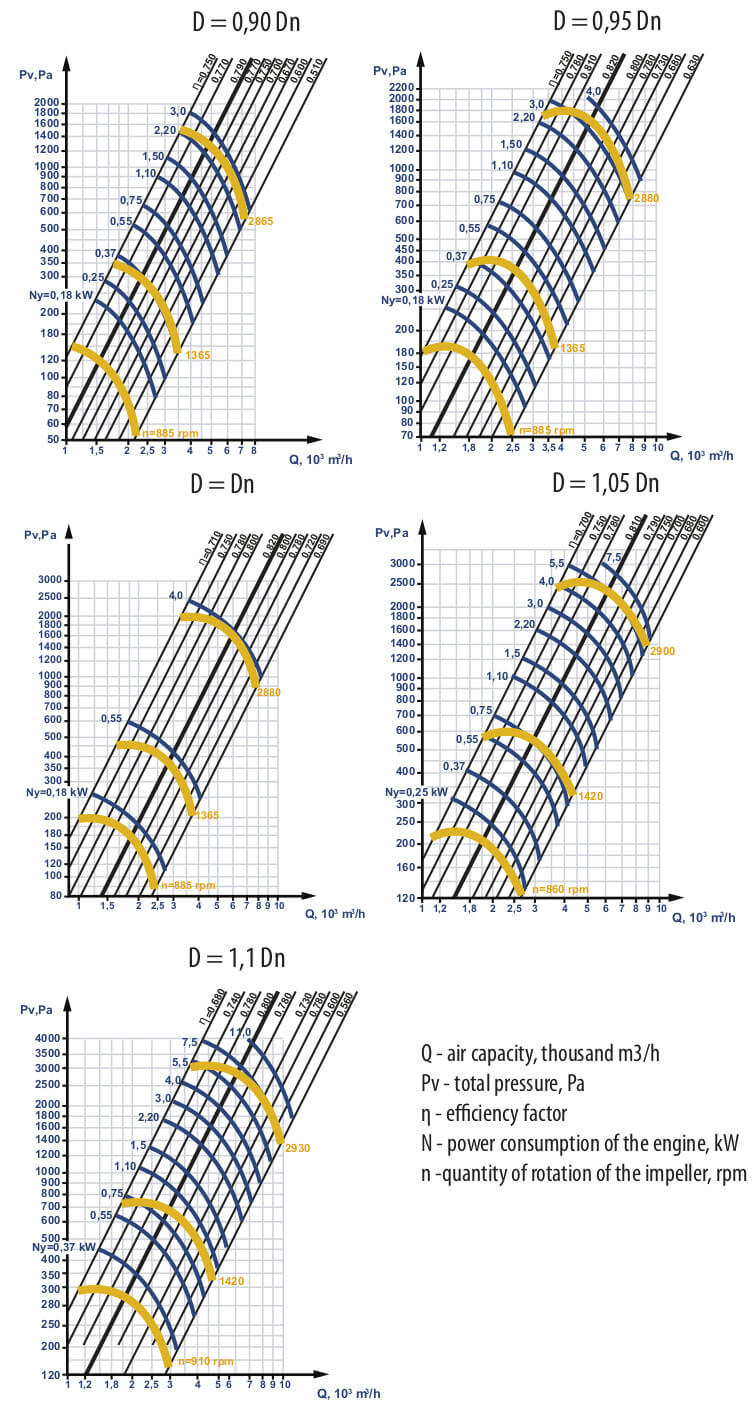
D/Dn – the diameter ratio fan impeller to the nominal diameter of the impeller. The impellers, which diameters differ from the nominal one, are called co-efficient impellers. The ratio of the diameter of the fan impeller to the nominal diameter of the impeller could be: 0.9, 0.95, 1.05, 1.1.
![]() |
|
Aerodynamic characteristics for fans
with reduced impeller diameter: D = 0,9 Dn and D = 0,95 Dn,
![]() |
![]() |
Aerodynamic characteristics for fans
with increased impeller diameter: D = 1,05 Dn and D = 1,1 Dn,
![]() |
![]() |
There are no reviews for this product.
There are no reviews for this product, be the first to leave your review.
No questions about this product, be the first and ask your question.