Popular


In Stock
Product Code: ID11105
18 797₴
Found cheaper?


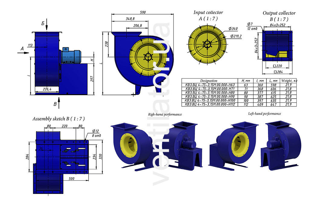
Low-pressure centrifugal fan VC 4-75 VZ #3.15 w/motor 4VR 63 A4 0.25 kW 1500 rpm manufactured according to design scheme #1. Equipped with brass overlays in friction zones for explosion protection.
Productivity, м³/h:1335
Pressure, Pa:232