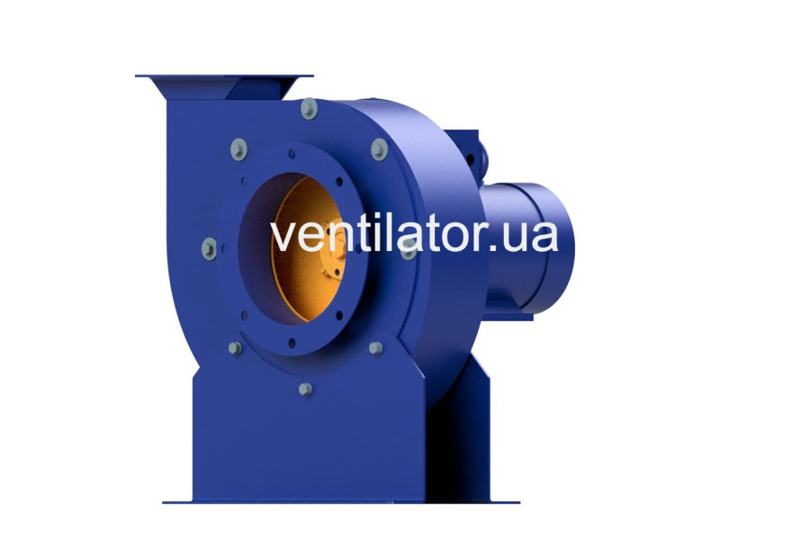
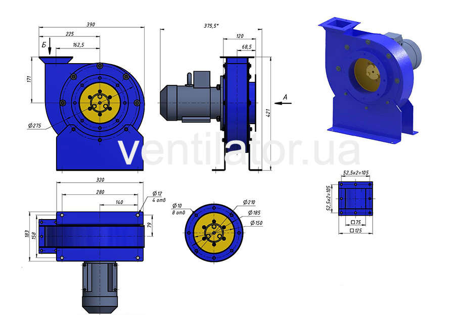
Average-pressure centrifugal fan series VC 10-28 (VR 200-28) #2,5 with electric motor Electric motor AIR 71 B2 1.1 Power kW 3000 Vol./Min, arranged according to the scheme of execution #1 the impeller on the motor shaft is made of carbon steel. Fan working point: 1050 m3/hour at pressure 1400 Pa.
VC 10-28 (BP 200-28) #2.5 w/motor AIR 71 B2 1.1 kW 3000 rpm, execution 1
The centrifugal fan medium pressure


Centrifugal Fan (Radial Fan) of Medium Pressure Series VC 10-28 (VR 200-28) #2,5 (VR 196-32.1)
The centrifugal fan (radial fan) of medium pressure series VC 10-28 (VR 200-28) #2,5 (VR 196-32.1) with an electric motor Electric motor AIR 71 B2 1.1 Power kW 3000 Vol./Min, designed according to execution scheme No. 1 with the impeller on the motor shaft, is made of carbon steel.
This fan is intended for moving air and other gas mixtures with corrosiveness relative to ordinary quality carbon steel not exceeding that of air, with a temperature up to +80°C, free from sticky substances, fibrous materials, and containing no more than 100 mg/m³ of dust and other solid impurities, suitable for moderate (U) climate, 3rd placement category, and tropical (T) climate, 2nd placement category as per DSTU 15150.
With protection of motors from atmospheric influences, the fans VC 10-28 (BP 200-28) #2.5 w/motor AIR 71 B2 1.1 kW 3000 rpm (VR 196-32.1) can be used in a moderate climate under 1st placement category per DSTU 15150. Ambient temperature ranges from -40°C to +40°C (+45°C for tropical climate versions).
General Information on Medium Pressure Centrifugal Fans VC 10-28 (BP 200-28) #2.5 w/motor AIR 71 B2 1.1 kW 3000 rpm (VR 196-32.1)
- Medium pressure;
- Single-sided suction;
- Spiral rotatable housing;
- Forward-curved blades;
- Number of blades: 48 pcs.;
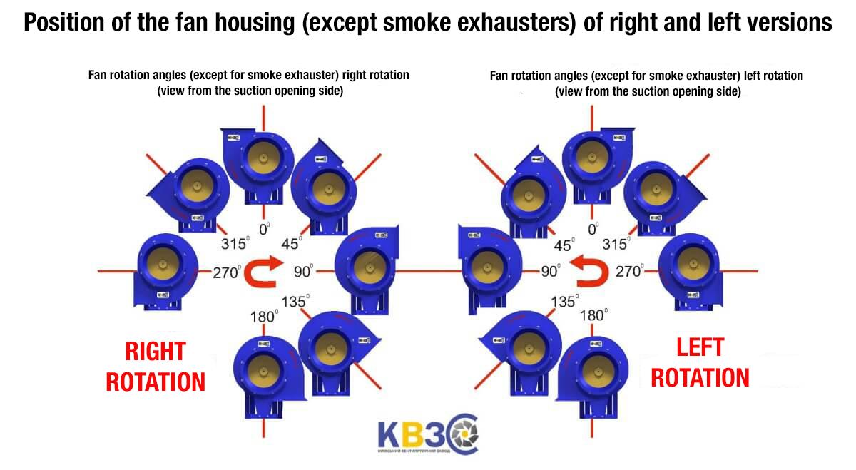
- Rotation direction: right and left;
- Material: carbon steel;
- Execution scheme: No. 1 – impeller on the motor shaft;
- Fans are manufactured in accordance with TU U 29.2-00909779-002-2007.
Applications of Medium Pressure Centrifugal Fans VC 10-28 (BP 200-28) #2.5 w/motor AIR 71 B2 1.1 kW 3000 rpm (VR 196-32.1)
Medium pressure centrifugal fans VC 10-28 (BP 200-28) #2.5 w/motor AIR 71 B2 1.1 kW 3000 rpm (VR 196-32.1) are used in stationary air conditioning and ventilation systems for industrial, public, and residential buildings, as well as for other sanitary-technical and industrial purposes.
Manufacturing Variants of Centrifugal Fans VC 10-28 (VR 200-28) #2,5 (VR 196-32.1) with Electric Motor Electric motor AIR 71 B2 1.1 Power kW 3000 Vol./Min
- Carbon steel;
- Stainless steel (custom order);
- Aluminum alloys (custom order);
- Heterogeneous metals (custom order).
Design and Operating Principle of Medium Pressure Centrifugal Fan Series VC 10-28 (VR 200-28) #2,5 (VR 196-32.1) with Electric Motor Electric motor AIR 71 B2 1.1 Power kW 3000 Vol./Min
Air movement is achieved by transferring the energy of the impeller’s rotation to the air.
The fan VC 10-28 (VR 200-28) #2,5 (VR 196-32.1) with electric motor Electric motor AIR 71 B2 1.1 Power kW 3000 Vol./Min consists of the following main components:
- Impeller;
- Spiral housing;
- Electric motor Electric motor AIR 71 B2 1.1 Power kW 3000 Vol./Min;
- Inlet nozzle;
- Bearing assembly (running gear);
- Bedplate;
- Frame.
Impeller of Fan VC 10-28 (VR 200-28) #2,5 (VR 196-32.1)
The impeller is of turbine type, featuring 48 blades. The blades are welded to the front and rear discs. The rear disc is attached to the hub by molding. The discs and blades are made of sheet steel, and the hub is made of gray cast iron. The impeller creates a vacuum in the suction zone and excess pressure in the discharge zone. It can rotate in either right or left direction.
Spiral Housing of Medium Pressure Fan VC 10-28 (VR 200-28) #2,5 (VR 196-32.1)
The spiral housing is welded from sheet and rolled steel. It can be designed for right or left rotation. The surfaces of the impeller and spiral housing in contact with the moved medium form a flow cavity. The housing shapes the suction and discharge flows.
Asynchronous Electric Motor Electric motor AIR 71 B2 1.1 Power kW 3000 Vol./Min
The electric motor Electric motor AIR 71 B2 is a general-purpose three-phase asynchronous motor with a short-circuited rotor, designed for operation from an AC network with a frequency of 50 Hz and voltage of 220/380 V. The motor Electric motor AIR 71 B2 has a nominal rotation speed of 3000 RPM. Dimensions: axis height 71 mm; shaft diameter 19 mm; power in kW: 1.1; climatic version: UZ; IP rating: 54. The housing of AIR motors with a power of 1.5 kW and above is cast from gray cast iron for reliable operation.
Inlet Nozzle
The inlet nozzle, made of steel sheet, serves to intake and direct the moved air into the impeller. The circular inlet nozzle is equipped with a flange for connecting the suction duct.
Bearing Assembly (Running Gear)
The running gear is designed to rotate the impeller. The bearing assembly consists of a shaft mounted on two bearing supports in a cast-iron housing. The impeller is attached to one end of the shaft, and the driven pulley is on the other. Sealing rings are provided in the bearing housing covers to prevent dust ingress. The bearing housing has a cavity for lubricant.
Bedplate
The bedplate is used to mount the bearing housing and spiral housing. It has a box-like shape and is made of sheet and rolled steel. The lower part of the bedplate has holes for mounting to the frame.
Frame
The fan frame, welded from rolled steel, supports all fan components. Holes in the lower plane of the frame are provided for mounting to the foundation.
Safety Precautions for Operating the Medium Pressure Fan VC 10-28 (VR 200-28) #2,5 (VR 196-32.1)
When installing, testing, and operating the fan VC 10-28 (BP 200-28) #2.5 w/motor AIR 71 B2 1.1 kW 3000 rpm (VR 196-32.1), the following safety requirements must be observed:
a) Personnel operating the fan must be familiar with its design, operating principles, and maintenance;
b) All rotating parts of the fan must be guarded;
c) Electrical equipment, inputs, and grounding must comply with the relevant sections of the current "Electrical Installation Regulations" (PUÉ) and DSTU 12.2.007.0-75;
d) All starting equipment must be located to allow observation of the fan’s startup process to prevent accidents;
e) Requirements for warning signals, signs, and labels are per clause 3.8 of DSTU 12.2.007.0-75.
Before starting the fan VC 10-28 (BP 200-28) #2.5 w/motor AIR 71 B2 1.1 kW 3000 rpm (VR 196-32.1), ensure no foreign objects are inside.
The worker starting the fan must stop all maintenance work and notify personnel of the startup.
In case of unusual noises or knocks in the fan or ductwork, immediately disconnect the fan by cutting off the power supply.
No maintenance work on the fan or ductwork is allowed until the fan has completely stopped.
During test runs, standing in the plane of the impeller’s rotation is prohibited.
When operating the fan without a suction line, the inlet nozzle must be covered with a protective mesh guard.
To avoid motor overload, start the fan with a closed throttle. Open the throttle smoothly.
Do not increase the impeller’s rotation speed beyond the limits specified in the fan’s documentation.
Loading and unloading operations must comply with DSTU 12.3.002-75 and DSTU 12.3.009-76.
For fans VC 10-28 (BP 200-28) #2.5 w/motor AIR 71 B2 1.1 kW 3000 rpm (VR 196-32.1) operating in areas with prolonged human presence, ventilation system designers must provide noise suppression measures to ensure noise levels at workplaces comply with DSTU 12.1.003-76. Ventilation systems in such cases must include flexible inserts, silencers, screens, or be installed in special sound-absorbing rooms (ventilation chambers). Noise levels at workplaces must comply with DSTU 20445-75.
The maximum root-mean-square speed of the fan impeller is no more than 6.7 mm/s at workplaces. Vibrations from the ventilation system must not exceed the values specified in DSTU 12.1.012-78.
Fan maintenance must be performed by specially trained electrical personnel.
A damaged flexible electrical cord increases the risk of electric shock or fire. The cord must not be stretched over sharp edges or exposed to heat or chemicals. All rotating parts must be guarded. The worker starting the fan must stop all maintenance or repair work on the fan and motor and notify personnel of the startup.
Ductwork must have devices to prevent foreign objects from entering the fan.
Electrical equipment installation and grounding of the fan and motor must comply with the "Electrical Installation Regulations" (PUÉ). The resistance between the grounding bolt and any accessible non-current-carrying metal part of the fan that may become energized must not exceed 0.1 Ohm.
Fan maintenance and repairs are allowed only after disconnection from the power supply and complete stopping of rotating parts.
During testing, adjustment, and operation, the suction and discharge openings must be guarded to prevent injuries, and operating the fan with removed or damaged ducts is prohibited.
During operation, regular preventive inspections and maintenance of the fan are necessary. Special attention should be paid to the gaps between the impeller and housing, the condition of ducts, impeller wear, blade damage, the reliability of the impeller’s mounting on the motor shaft, and the grounding condition of the fan and motor. Securely fix the fan to the foundation and
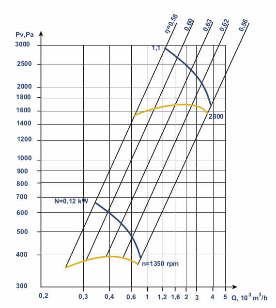
VC 10-28 fan aerodynamic characteristics, Modification 1, D=Dn
at barometric pressure of 760 mm Hg. Art. and temperature 20 ° С
There are no reviews for this product.
There are no reviews for this product, be the first to leave your review.
No questions about this product, be the first and ask your question.